Operating Principle
Injection Sequence for a Single-Needle System
Preparing for Sample Drawing
Before the start of an injection sequence or during an analysis, the injection valve is in the mainpass (main path) position. In this position, the mobile phase passes through all flow path components in contact with the sample, such as the loop capillary, to ensure that they are constantly flushed by the flow, minimizing carry over.
The injection sequence begins with the injection valve switching to the bypass position, which diverts the flow from the pump directly towards the column (from port 1 to port 6), while leaving out the components of the sample introduction system.
For a standard wash system, the seat capillary is then connected to the waste line (from port 5 to port 4). Thus, when the metering plunger moves forward to return to the home position, some eluent is pushes out through the waste tube towards the waste handling system. The volume of the ejected liquid equals the injection volume of the previous run.
For a Multiwash system, the seat capillary is not connected to the waste line but to the flush pump of the needle seat backflush system (from port 5 to port 4) when the injection valve is in the bypass position. To allow the escape of the eluent pushed out when the metering plunger returns to the home position, the needle lifts by a couple of millimeters above the needle seat. The ejected liquid might build a droplet on the needle seat depending on its volume, which equals the injection volume of the previous run.
NOTE
When the Multiwash option is installed, it must be used to wash away droplets created on the needle seat after each injection.
Sample Drawing
As soon as the metering plunger is back in the home position, the robotic arm lifts the needle assembly from the park station, moves it to the central workstation, and lowers it into the vial or wellplate with the sample of interest. The metering plunger then starts to move back, drawing the sample into the loop capillary. Finally, the robotic arm moves the needle assembly back to the park station and lowers it into the needle seat to close the flow path. In the case of an injector program, the system might perform additional sample preparation steps at this point, such as mixing or standard addition.
Flushing the Needle (Standard Wash)
When high sensitivity is needed, the outer surface of the needle can be rinsed in the flush port located behind the injector port before the injection of the sample to reduce carryover.
At the start of the wash process, a small air plug is introduced into the needle tip to prevent any undesired sample loss. Then, the needle moves into the flush port, and the peristaltic pump starts delivering wash solvent for a predefined time at a rate of 6 mL/min. The fresh wash solvent enters through the inlet port at the bottom, whereas the exhausted solvent leaves at the top edge of the flush port towards the waste handling system. This concept ensures that the needle tip is constantly exposed to clean wash solvent. At the end of the wash procedure, the needle returns to the needle seat
Flushing the Needle (Multiwash)
With the Multiwash option, the outer surface of the needle can be rinsed with not one but three different wash solvents, reducing the carryover to as low as the level of 9 ppm, which ultimately allows for ultra-low sensitivity analyses.
At the start of the wash process, a small air plug is introduced into the needle tip to prevent any undesired sample loss. Then, the needle moves into the flush port, and the piezo pump starts delivering wash solvent for a predefined time at a rate of 4 mL/min. The solvent selection valve enables the system to switch between three different wash solvents during the wash procedure in a user-defined order. The fresh wash solvent enters through the inlet port at the bottom, whereas the exhausted solvent leaves at the top edge of the flush port towards the waste handling system.
Inject-and-Run
During the inject-and-run step, the six-port valve switches to the mainpass (main path) position and directs the flow towards the sample loop, which marks the beginning of the run in the chromatography data system (CDS). The eluent then transports the sample from the loop capillary onto the column, where the separation begins. Thanks to the flow-through design of the injection system, the components of the flow path are constantly flushed by the solvent flow, reducing carryover significantly. For standard applications, no additional flushing procedure is required.
NOTE
When the Multiwash option is installed, it must be used to wash away droplets created on the needle seat after each injection.
Needle seat back flush
With the Multiwash option, the system can backflush the needle seat capillary with the help of a dedicated flush pump at the end of each injection cycle, which has paramount importance when high sensitivity is needed.
After the injection valve switches into the bypass position, the solvent selection valve diverts the wash solvent stream towards the flush pump, allowing the system to use the same three solvents available for needle wash. The flush pump then presses the wash solvent through the needle seat capillary via the injection valve (from port 4 to port 5) in the reverse direction to remove any contamination that may reside there. The exhausted wash solvent leaves through the inlet port of the needle seat and drains through the leak system of the needle wash port. During the seat backflush procedure, the solvent selection switches between the different wash solvents in a user-defined order.
It is recommended to use the starting mobile phase composition as the wash solvent in the last rinsing step to avoid any undesired solvent interaction with your chromatography.
NOTE
It takes approximately 30 s to fully exchange one solvent for another in the flush port, and 18 s in the seat. Also, it is recommended to use the autoclean function (right-click the dashboard and select Auto-clean) to flush the multisampler regularly with all installed solvents.
NOTE
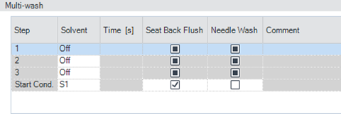
If Seat Back Flush and Needle Wash are both activated at the same time, they must use the same solvent.
NOTE
It is recommended to always activate Start Cond. as the last step of the washing procedure. The flow path is then filled with the appropriate starting solvent conditions for the next sample.
NOTE
It is not recommended to use buffers and solvents with high salt content as the last step of the washing procedure. This might cause formation of salt crystals on the needle seat.
NOTE
Due to the flow path of the Multiwash hydraulic box (see Valve in bypass, needle seat backflush (Multiwash)), when the metering device moves to home position before an injection, a droplet of clean mobile phase will come out from the needle tip and might fall into the seat. This is an expected behavior, independent of the Injection Path Cleaning settings, and does not indicate leakage.
To avoid salt build-up on the needle and the seat when using buffers and solvents with high salt content as mobile phase, follow these recommendations:
- Purge the Multisampler daily with water for 15 min.
- Visually inspect the needle and seat.
Injection Sequence for Dual Needle (Bypass Mode)
This corresponds to the injection sequence for single needles, see Injection Sequence for a Single-Needle System. Only one flow path is used on a regular basis, and a defined bypass capillary replaces either the left or the right dual-needle sample loop. This bypass capillary shortcuts one path to allow faster reconditioning.
Injection Sequence for Dual Needle (Alternating Mode)
Flushing the system
The Start of the pump or changes in solvent composition trigger the purge routine of the multisampler. The purge routine flushes the hydraulic setup of the multisampler with fresh mobile phase (for example metering device, sample loops, and needles). This ensures cleanness of the flowpath.
NOTE
For pumps with a manual purge valve, it is mandatory to start the purge routine before a run or sequence. This will guarantee that the complete flow path of the dual-needle setup is flushed with fresh mobile phase.
The robot moves the wellplates or vial trays from the sample hotel to the central workspace. The injection valve unit switches to the mainpass (main path) (left) position. Then the sampling process starts. Solvent from the pump enters the peripheral valve at port 2, and flows through port 1 directly to the injection valve. The solvent enters the injection valve at port 2, flows via port 1 through the sample loop (left), the needle (left), the needle seat (left), port 5 and port 6 to the column.
Drawing sample (right)
Then the needle assembly (right) moves to the desired sample position and immerses into the sample. The plunger of the metering device moves back and draws up the desired volume. Then the needle assembly (right) raises and moves to the needle park station on the needle seat (right). This closes the sample loop (right).
Flush the Needle (if selected)
To reduce carryover, the outside of the left or the right needle can be washed in the flush port that is located behind the needle park station. As soon as the needle is on the flush port, a wash pump flushes the outside of the needle for a defined time (defined for example in the method). After this process the needle assembly returns to the appropriate needle park station. This closes the sample loop (right).
Alternating Dual-needle Inject and Run (Right needle)
The eight port valve switches to the mainpass (main path) (right) position. Now Port 2 and 3 and Port 7 and 6 of the injection valve are connected. This directs the flow through the sample loop (right) and the solvent transports the sample to the column. Separation and analysis starts. In the meantime, the flow path (right) is flushed internally by the solvent.
Prepare Inject and Run of the alternating dual needle (left needle)
The sample container is in the central sample work space. The robot detaches the needle assembly (left) from the needle port. The metering device drives to the home position. Then the needle assembly (left) is moved to the desired sample position and immerses into the sample. The plunger of the metering device moves back and draws up the desired volume. Then the needle assembly (left) raises and moves to the needle park station on the needle seat (left). This closes the sample loop (left).
The left needle can be flushed as the right needle, see description above.
The eight port valve switches to the mainpass (main path) (left) position. Now Port 2 and 1 and Port 5 and 6 of the injection valve are connected. This directs the flow through the sample loop (left) and the solvent transports the sample to the column. Separation and analysis starts. In the meantime, the flow path (left) is flushed internally by the solvent.
The alternating flush and injection cycles minimize injection cycle times and ensure maximal cleanness of the hardware.
Multi-load with Dual needle (left needle)
In the multi-load mode, the peripheral valve switches in different positions while the plunger of the metering device moves back and forward. At the same time, the needle remains in the sample vial or well. That way the multi-load technique allows to draw multiple times and inject large sample volumes. This multi-load technique is completely different from the multi-draw technique that is used in other autosamplers.
base-id: 3981777675
id: 9007203236518667