Mounting the Valve Drive to a G7116A/B Multicolumn Thermostat
Parts required
Qty. | p/n | Description | |
|---|---|---|---|
1 |  | 5067-6138 | Infinity II & III Valve Holder Kit Right , or |
1 | | 5067-6139 | Infinity II & III Valve Holder Kit Left |
-
Ensure the power switch at the rear of the module is OFF and the power connector is unplugged.
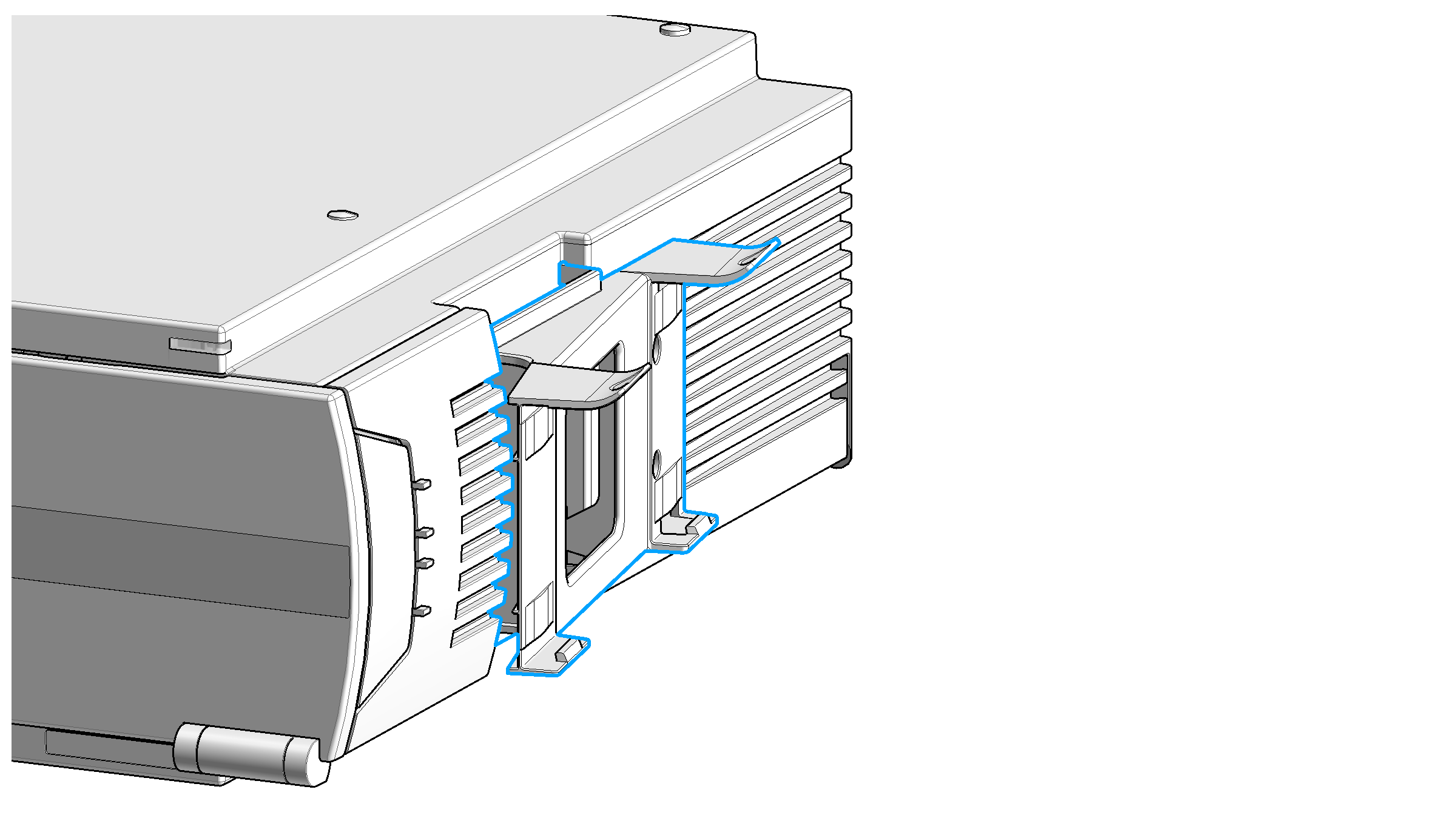
Identify the marks for the screws on the side of the Infinity II/III MCT cabinet and screw the valve clamp to the side panel of the cabinet using the screws from the kit.
-
Slide the first clamp on to one side of the valve drive housing.
-
Install the leak tray and leak sensor to the valve.
Slide the second clamp on to the same side as the first one.
Attach the waste tubing to the leak plane and guide it to a proper waste container.
Connect the power cable to the power connector at the rear of the module.
Connect the CAN interface connection.
-
Power on the module by switching the Power button at the rear of the module if a valve head has been already installed. Otherwise continue with G7116B_Installation of the Valve Heads.
base-id: 3181741579
id: 9007202436482571