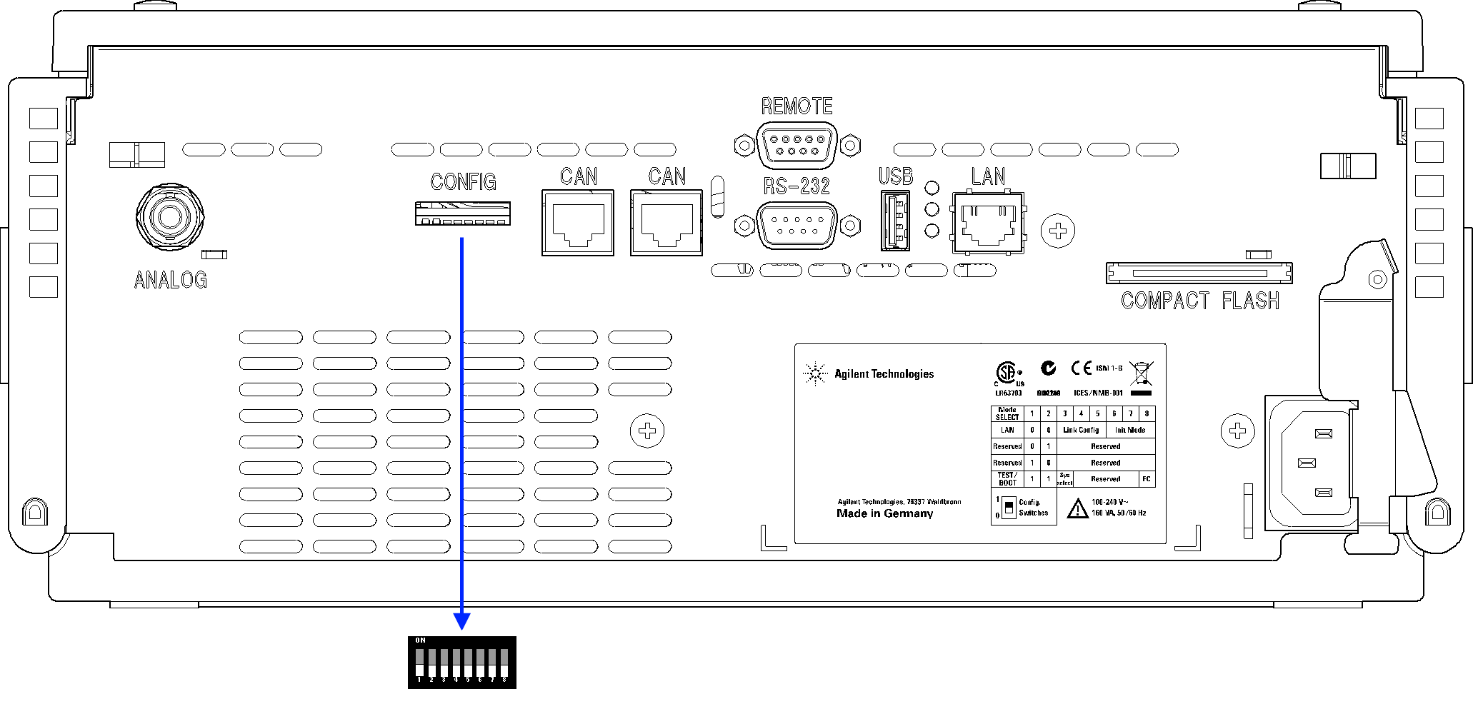
Setting the 8-bit Configuration Switch (On-Board LAN)
The 8-bit configuration switch is located at the rear of the module. Switch settings provide configuration parameters for LAN, serial communication protocol and instrument specific initialization procedures.
All modules with on-board LAN:
Default is ALL switches DOWN (best settings).
19200 baud, 8 data bit / 1 stop bit with no parity for RS-232
For specific LAN modes switches 3-8 must be set as required.
For boot/test modes switches 1+2 must be UP plus required mode.
NOTE
For normal operation use the default (best) settings.
NOTE
To perform any LAN configuration, SW1 and SW2 must be set to OFF. For details on the LAN settings/configuration refer to chapter LAN Configuration.
|
|
Mode |
|
Function |
|
|
|
|
|
|
| SW 1 |
SW 2 | SW 3 | SW 4 |
SW 5 | SW 6 | SW 7 |
SW 8 |
| LAN | 0 | 0 | Link Configuration | Init Mode Selection | ||||
| Auto-negotiation | 0 | x |
x | x |
x | x | ||
| 10 MBit, half-duplex | 1 | 0 | 0 | x |
x | x | ||
| 10 MBit, full-duplex | 1 | 0 | 1 |
x | x |
x | ||
| 100 MBit, half-duplex | 1 |
1 | 0 | x |
x | x | ||
| 100 MBit, full-duplex | 1 |
1 | 1 |
x | x |
x | ||
| Using Stored | x |
x | x | 0 | 1 | 0 | ||
| DHCP | x |
x | x | 1 |
0 | 0 | ||
| Using Default | x |
x | x | 0 | 1 |
1 | ||
| Test |
1 | 1 |
System |
|
|
|
|
NVRAM |
| Boot Resident System | 1 |
|
|
|
|
x | ||
| Revert to Default Data (Coldstart) |
x | x |
x |
|
| 1 | ||
Legend:
0 (switch down), 1 (switch up), x (any position), SW (switch)
NOTE
When selecting the mode Test, the LAN settings are: Auto-Negotiation & Using Stored.
NOTE
For explanation of "Boot Resident System" and "Revert to Default Data (Coldstart)" refer to Special Settings.
Subpages
base-id: 4133509515
id: 4133509515-1