Special Settings
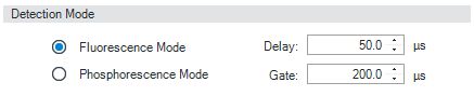
| Detection Mode Default: Fluorescence Choose the Fluorescence Mode option to measure luminescence from samples that emit fluorescence.
Choose the Phosphorescence Mode option to measure luminescence from samples that emit phosphorescence. When you choose to switch on the Phosphorescence detection mode, the two parameters Delay and Gate are activated.
The luminescence that you measure with the fluorescence detector has different characteristics depending on the chemistry of your application. The characteristic of your sample determines whether you need to use fluorescence detection mode or phosphorescence detection mode.
Delay Sets a waiting period, during which the lamp flashes, before the FLD starts to measure.
Limits: 0 – 5000.0 µs in steps of 0.1 µs.
Gate Sets a measurement time period after the lamp has flashed.
Limits: 20.0 – 5000.0 µs in steps of0.1 µs. |
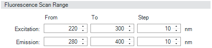
| Fluorescence Scan Range (G7121B ONLY) The Fluorescence Scan Range panel enables you to set up a fluorescence scan (3D scan). The fluorescence scan can be used to collect emission and excitation spectral information in a single task. It is most suitable for the characterization of single compounds, and for checking the purity of eluents. The contents of the flow cell must be kept constant during the measurement; use off-line measurements with the FLD cuvette or stopped-flow conditions in chromatography.
Enter the wavelength ranges for excitation and emission. The Step size determines the number of data points per spectrum. The time per scan (in seconds) is calculated automatically and displayed. |
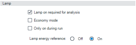
| The Lamp section allows you to specify how the lamp is used in an analysis.
Select Only On During Run to specify that the lamp is switched on only during the run time, and is switched off when the run finishes.
Select Economy Mode to run the lamp in a low frequency, low current mode. This increases the lamp lifetime at the expense of sensitivity.
To prolong the life of the lamp, clear the check box if you have a multiple detector configuration and do not want to use the FLD for the next analyses.
NOTE: If the Lamp on required for analysis check box is marked, but the lamp is off when the run is started, the lamp is switched on automatically.
Lamp Energy Reference Choose On to switch on a compensation for flash-to-flash variations in lamp intensity using the reference diode. This gives improved signal-to-noise. |
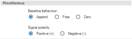
| Baseline Behavior Baseline behavior allows you to choose what happens to the baseline after a change in wavelength or PMT gain.
Signal Polarity Select the Signal Polarity you expect from your data from Negative or Positive. |
base-id: 3586946827
id: 3586946827