Advanced Settings
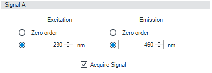
| Signal A You can define the wavelengths of the excitation and emission and specify signal acquisition.
Limits (Ex and Em): 200 to 1200 nm in steps of 1 nm.
NOTE: The emission wavelength should be at least 10 nm greater than the excitation wavelength
NOTE: Addition signals B, C, D can be added via Mulitiple Wavelength mode (G721B ONLY).
Zero Order (Ex) The full spectrum of light from the Xenon lamp illuminates the flow cell. Each compound can absorb its characteristic wavelength of light and then emit maximum fluorescence. An increased stray light level is inherent in this setting, and this will decrease sensitivity (signal-to-noise).
Zero Order (Em) Zero order sets the monochromator so that all light emitted from the sample will be reflected onto the detector. Acquire Signal Mark this check box to specify that the signal is stored in the CDS during data acquisition. When the check box is cleared, the signal is not stored. |
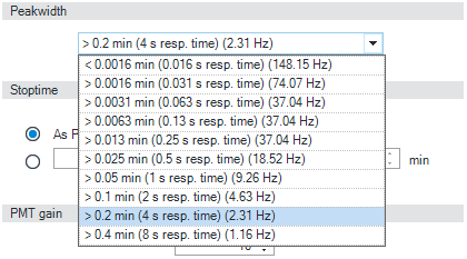
Peakwidth Settings (G7121B)
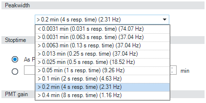
Peakwidth Settings (G7121A) | Peakwidth (Responsetime, Data Rate) Peakwidth enables you to select the peak width (response time) for your analysis. The peak width is defined as the width of a peak, in minutes, at half the peak height. Set the peak width to the narrowest expected peak in your chromatogram. The peak width sets the optimum response time for your FLD. The peak detector ignores any peaks that are considerably narrower, or wider, than the peak width setting. The response time is the time between 10 % and 90 % of the output signal in response to an input step function. Limits: When you set the peak width (in minutes), the corresponding response time is set automatically and the appropriate data rate for signal and spectra acquisition is selected as shown. |
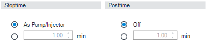
| Stoptime/Posttime The Stoptime is the time where either the complete system stops (As Pump/Injector) or the module (if different from system stop time). The data collection is stopped at this time. A Posttime period can be used to allow module’s items to equilibrate (e.g. after gradient change or temperature change). |
| PMT Gain is the photomultiplier gain. Each step approximately doubles the signal. A typical setting is between 10 and 15 ; use lower settings for very high concentrations. Higher PMT Gain may improve signal-to-noise. See also FLD Scaling Range and Operating Conditions.
Limits: 0 to 18 in steps of 1 . Default value is 10 |
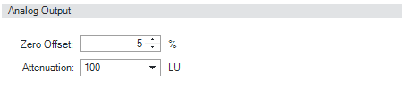
| Analog Output The range can be set to either 100 mV100 or 1 V1 full scale, see Detector Control Settings .
|
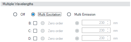
| Multiple Wavelengths (G7121B ONLY) You can choose to use three additional wavelengths, either excitation or emission wavelengths in your analysis. Choose Off to switch off multiple wavelengths, or Multi Ex or Multi Em to set up multiple wavelengths.
See also Signal A.
|

base-id: 3586937867
id: 3586937867