ERI (Enhanced Remote Interface)
ERI replaces the AGP Remote Interface that is used in the HP 1090/1040/1050/1100 HPLC systems and Agilent 1100/1200/1200 Infinity HPLC modules. All new InfinityLab LC Series products using the communication board use ERI. This interface is already used in the Agilent Universal Interface Box 2 (UIB2)
Remote (ERI)
The ERI (Enhanced Remote Interface) connector may be used in combination with other analytical instruments from Agilent Technologies if you want to use features as common shut down, prepare, and so on.
It allows easy connection between single instruments or systems to ensure coordinated analysis with simple coupling requirements.
The subminiature D connector is used. The module provides one remote connector which is inputs/outputs (wired- or technique).
To provide maximum safety within a distributed analysis system, one line is dedicated to SHUT DOWN the system’s critical parts in case any module detects a serious problem. To detect whether all participating modules are switched on or properly powered, one line is defined to summarize the POWER ON state of all connected modules. Control of analysis is maintained by signal readiness READY for next analysis, followed by START of run and optional STOP of run triggered on the respective lines. In addition PREPARE and START REQUEST may be issued. The signal levels are defined as:
standard TTL levels (0 V is logic true, + 5.0 V is false),
fan-out is 10,
input load is 2.2 kOhm against + 5.0 V, and
output are open collector type, inputs/outputs (wired- or technique).
NOTE
All common TTL circuits operate with a 5 V power supply. A TTL signal is defined as "low" or L when between 0 V and 0.8 V and "high" or H when between 2.0 V and 5.0 V (with respect to the ground terminal).
Pin | Signal | Description |
|---|---|---|
|
1 |
START REQUEST |
(L) Request to start injection cycle (for example, by start key on any module). Receiver is the autosampler. |
|
2 |
STOP |
(L) Request to reach system ready state as soon as possible (for example, stop run, abort or finish and stop injection). Receiver is any module performing run-time controlled activities. |
|
3 |
READY |
(H) System is ready for next analysis. Receiver is any sequence controller. |
|
4 |
POWER ON |
(H) All modules connected to system are switched on. Receiver is any module relying on operation of others. |
|
5 |
|
Not used |
|
6 |
SHUT DOWN |
(L) System has serious problem (for example, leak: stops pump). Receiver is any module capable to reduce safety risk. |
|
7 |
START |
(L) Request to start run / timetable. Receiver is any module performing run-time controlled activities. |
|
8 |
PREPARE |
(L) Request to prepare for analysis (for example, calibration, detector lamp on). Receiver is any module performing pre-analysis activities. |
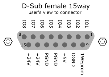
ERI Description
The ERI interface contains eight individual programmable input/output pins. In addition, it provides 24 V power and 5 V power and a serial data line to detect and recognize further add-ons that could be connected to this interface. This way the interface can support various additional devices like sensors, triggers (in and out) and small controllers, etc.
| Pin | Enhanced Remote |
|---|---|---|
|
|
1 |
IO 1 (START REQUEST) |
|
2 |
IO 2 (STOP) | |
|
3 |
IO 3 (READY) | |
|
4 |
IO 4 (POWER ON) | |
|
5 |
IO 5 (NOT USED) | |
|
6 |
IO 6 (SHUT DOWN) | |
|
7 |
IO 7 (START) | |
|
8 |
IO 8 (PREPARE) | |
|
9 |
1 wire DATA | |
|
10 |
DGND | |
|
11 |
+5 V ERI out | |
|
12 |
PGND | |
|
13 |
PGND | |
|
14 |
+24 V ERI out | |
|
15 |
+24 V ERI out |
IO (Input/Output) Lines
Eight generic bi-directional channels (input or output).
Same as the APG Remote.
Devices like valves, relays, ADCs, DACs, controllers can be supported/controlled.
1-Wire Data (Future Use)
This serial line can be used to read out an EPROM or write into an EPROM of a connected ERI-device. The firmware can detect the connected type of device automatically and update information in the device (if required).
5V Distribution (Future Use)
Available directly after turning on the hosting module (assures that the firmware can detect certain basic functionality of the device).
For digital circuits or similar.
Provides 500 mA maximum.
Short-circuit proof with automatic switch off (by firmware).
24V Distribution (Future Use)
Available by firmware command (defined turn on/off).
For devices that need higher power
Class 0: 0.5 A maximum (12 W)
Class 1: 1.0 A maximum (24 W)
Class 2: 2.0 A maximum (48 W)
Class depends on hosting module’s internal power overhead.
If a connected device requires more power the firmware detects this (overcurrent detection) and provides the information to the user interface.
Fuse used for safety protection (on board).
Short circuit will be detected through hardware.
base-id: 3002194315
id: 18014401511676299