Remote Cables
ERI (Enhanced Remote Interface)
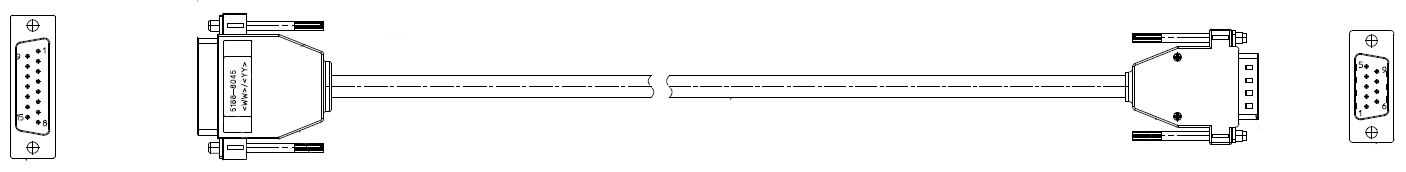
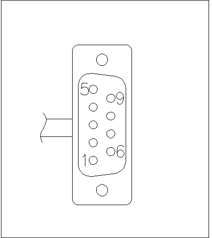
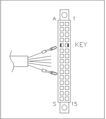
5188-8029 ERI to general purpose (D-Sub 15 pin male - open end)
5188-8044 ERI to ERI (D_Sub 15 pin male - male)
5188-8059 ERI-Extension-Cable 1.2 m (D-Sub15 pin male / female)
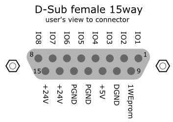
p/n 5188-8029 | pin | Color code | Enhanced Remote | Classic Remote | Active (TTL) |
|---|---|---|---|---|---|
| 1 | white | IO1 | START REQUEST | Low |
2 | brown | IO2 | STOP | Low | |
3 | green | IO3 | READY | High | |
4 | yellow | IO4 | PEAK DETECT | Low | |
5 | grey | IO5 | POWER ON | High | |
6 | pink | IO6 | SHUT DOWN | Low | |
7 | blue | IO7 | START | Low | |
8 | red | IO8 | PREPARE | Low | |
9 | black | 1wire DATA |
|
| |
10 | violet | DGND |
|
| |
11 | grey-pink | +5V ERI out |
|
| |
12 | red-blue | PGND |
|
| |
13 | white-green | PGND |
|
| |
14 | brown-green | +24V ERI out |
|
| |
15 | white-yellow | +24V ERI out |
| ||
NC | yellow-brown |
|
|
|
NOTE
Configuration is different with old firmware revisions.
The configuration for IO4 and IO5 is swapped for modules with firmware lower than D.07.10.
NOTE
Peak Detection is used for LCMS systems connected with the Fraction Collection Remote Y-Cable (5188-8057).
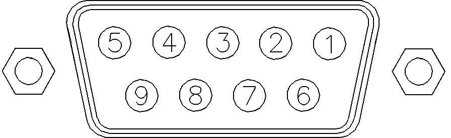
5188-8045 ERI to APG (Connector D_Subminiature 15 pin (ERI), Connector D_Subminiature 9 pin (APG))
p/n 5188-8045 | Pin (ERI) | Signal | Pin (APG) | Active (TTL) |
|---|---|---|---|---|
|
|
10 |
GND |
1 |
|
|
1 |
Start Request |
9 |
Low | |
|
2 |
Stop |
8 |
Low | |
|
3 |
Ready |
7 |
High | |
|
5 |
Power on |
6 |
High | |
|
4 |
Future |
5 |
| |
|
6 |
Shut Down |
4 |
Low | |
|
7 |
Start |
3 |
Low | |
|
8 |
Prepare |
2 |
Low | |
|
Ground |
Cable Shielding |
NC |
|
5188-8057 ERI to APG and RJ45 (Connector D_Subminiature 15 pin (ERI), Connector D_Subminiature 9 pin (APG), Connector plug Cat5e (RJ45))
p/n 5188-8057 | Pin (ERI) | Signal | Pin (APG) | Active (TTL) | Pin (RJ45) |
|---|---|---|---|---|---|
|
|
|
|
|
|
|
|
10 |
GND |
1 |
|
5 | |
|
1 |
Start Request |
9 |
High |
| |
|
2 |
Stop |
8 |
High |
| |
|
3 |
Ready |
7 |
High |
| |
|
4 |
Fraction Trigger |
5 |
High |
4 | |
|
5 |
Power on |
6 |
High |
| |
|
6 |
Shut Down |
4 |
High |
| |
|
7 |
Start |
3 |
High |
| |
|
8 |
Prepare |
2 |
High |
| |
|
Ground |
Cable Shielding |
NC |
|
|
One end of these cables provides an Agilent Technologies APG (Auxiliary Port Group) remote connector to be connected to Agilent modules. The other end depends on the instrument to be connected to.
Agilent Module to Agilent 35900 A/D Converters
p/n 5061-3378 | Pin 35900 A/D | Pin Agilent module | Signal Name | Active (TTL) |
|---|---|---|---|---|
|
|
1 - White |
1 - White |
Digital ground |
|
|
2 - Brown |
2 - Brown |
Prepare run |
Low | |
|
3 - Gray |
3 - Gray |
Start |
Low | |
|
4 - Blue |
4 - Blue |
Shut down |
Low | |
|
5 - Pink |
5 - Pink |
Not connected |
| |
|
6 - Yellow |
6 - Yellow |
Power on |
High | |
|
7 - Red |
7 - Red |
Ready |
High | |
|
8 - Green |
8 - Green |
Stop |
Low | |
|
9 - Black |
9 - Black |
Start request |
Low |
Agilent Module to General Purpose
p/n 01046-60201 | Wire Color | Pin Agilent module | Signal Name | Active (TTL) |
|---|---|---|---|---|
|
|
White |
1 |
Digital ground |
|
|
Brown |
2 |
Prepare run |
Low | |
|
Gray |
3 |
Start |
Low | |
|
Blue |
4 |
Shut down |
Low | |
|
Pink |
5 |
Not connected |
| |
|
Yellow |
6 |
Power on |
High | |
|
Red |
7 |
Ready |
High | |
|
Green |
8 |
Stop |
Low | |
|
Black |
9 |
Start request |
Low |
base-id: 3002141579
id: 18014401511623563